Blueshawk Wiring
Rewiring a Gibson Blueshawk for simplicity and lower noise.
Gibson Blueshawk
The Gibson Blueshawk is a lovable oddball of a guitar. You could think of it as Gibson's take on a kind of Telecaster by its 25.5" scale neck and 2-single-coil pickup arrangement, but I think it's comfortably in its own category. Blueshawks are semi-hollow with a maple cap on a poplar body which keeps the weight down, and a glued-in mahogany neck with rosewood fretboard.
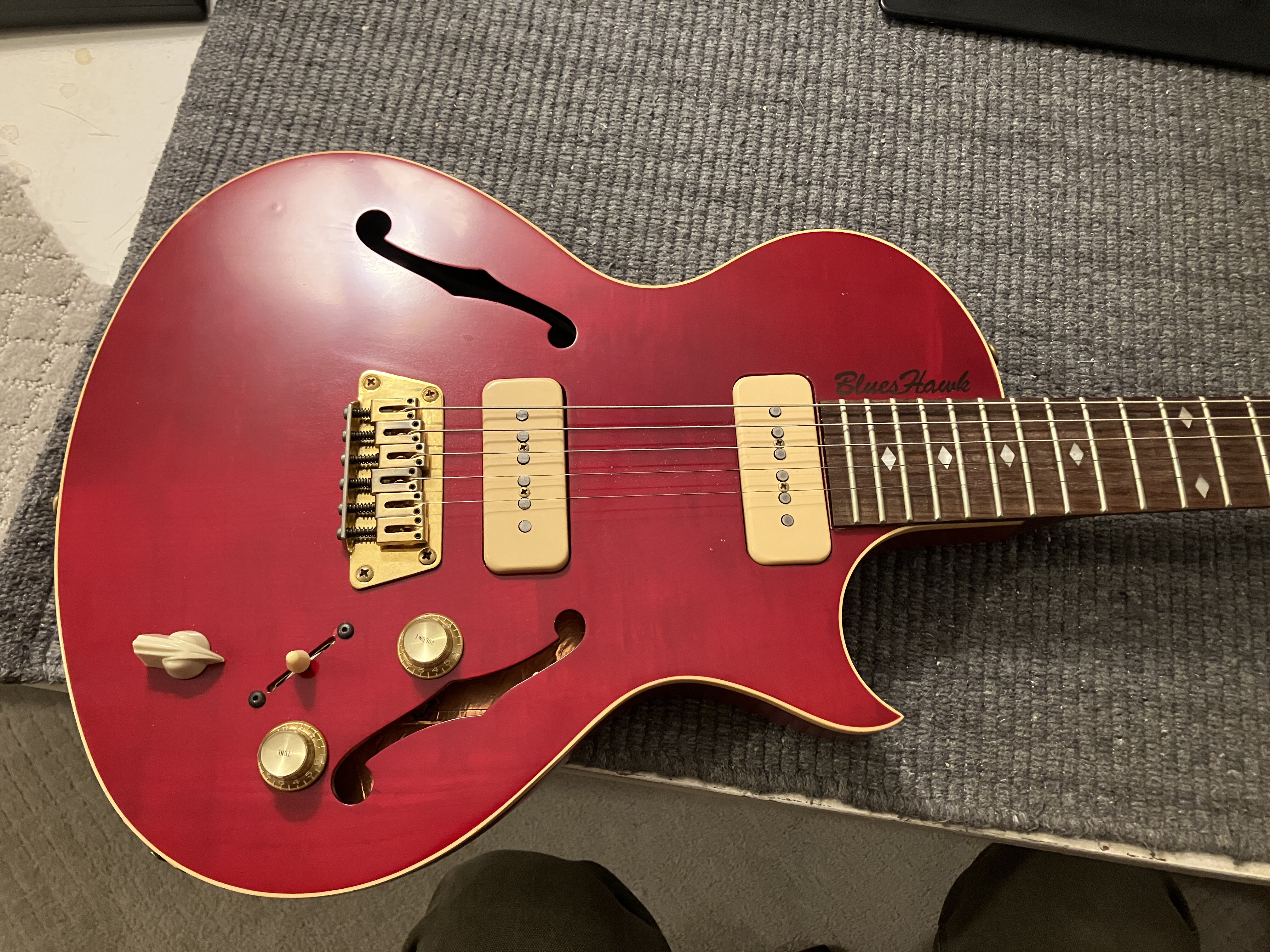
Figure 1: pay no attention to that missing string
But anybody with an internet connection can tell you all that. This post will focus on correcting some myths regarding its electronics and also describe how I modified mine for lower noise.
Essentials
Gibson's Blueshawk has two single-coil pickups, master tone/volume, a 3-way blade switch for pickup selection, and a 6-position rotary switch for a Varitone circuit. The tone pot is a push-pull type that lets you bypass the Varitone.
Nitty-Gritty Details
The overall schematic from the factory looks like this:

Figure 2: Blueshawk original wiring
Potentiometers
The volume pot is 300kΩ and linear. The value is a little high but understandable if you want to preserve brightness. What's strange is the choice to use a linear taper pot instead of an audio taper. In my experience this makes the volume pot annoying to use, as the first 2/3 of its rotation makes almost no difference to the level. There is a treble bleed cap on the volume pot however, which helps retain the high frequency content as you turn the volume down.
The tone pot is 500k, log taper.
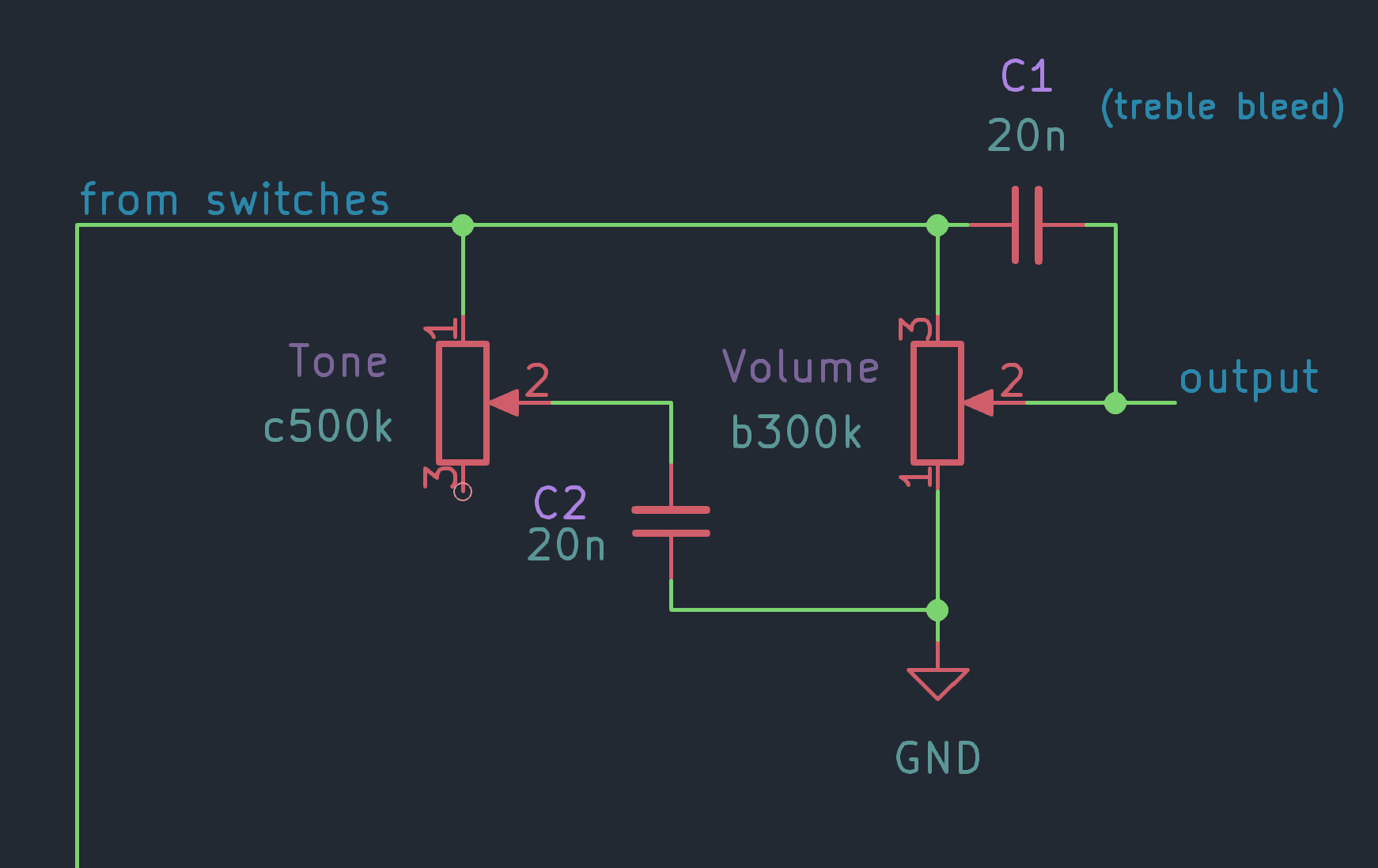
Figure 3: Blueshawk potentiometers
Pickup Selector Switch
This is where it gets a little crazy. Most Gibson guitars with 2 pickups and a neck/both/bridge selector use a bat-style selector switch. Here we havea a blade-style switch. But this is not a typical 2p3t selector. Instead we have a 4-pole, 3-throw switch, made from 4 independent 1p3t sections.
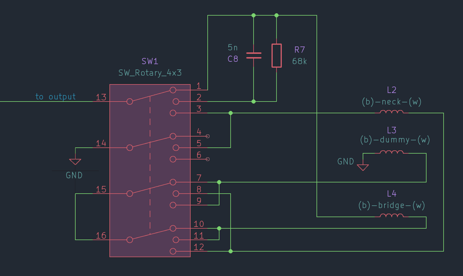
Figure 4: Blueshawk 4p3t switch and pickups
In this part of the schematic the labels (b) and (w) stand for black and white wires from the pickups, although in my case the white wire is more of a pale blue.
Varitone
This is a resonant circuit with a choke (7.2H inductor) and capacitor to ground in parallel with the pickup. A resistor in series with this resonant circuit dampens it otherwise it would be a drastic volume cut. With the resistor it acts like a midrange cut. There are 5 different capacitor options on the 6-way switch; the remaining switch position does not select any resonant circuit.
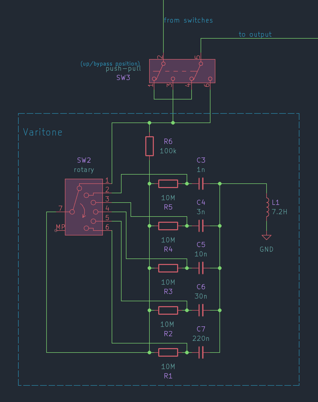
Figure 5: Varitone
In addition, there is a DPDT switch to bypass the resonant circuit entirely. This switch is part of the push-pull tone pot.
Fighting Misinformation
Myth 1: these are not P90 pickups (100% false)
Many people make the mistake of thinking the pickups in the Blueshawk are P-90 pickups. While they use the same soapbar-shaped cover and look almost the same from the outside, inside they are different. P90s have two bar magnets below the coil, facing inward at steel screws which act as pole pieces. The "Blues 90" pickups in the Blueshawk have magnetic pole pieces and lower impedance. They sound thinner and have lower output compared to most P90 pickups. The only outward clue of the difference is that the Blues 90 pickups do not have screw heads for pole pieces, whereas most (all?) P90s do.
There is a parallel resistor+capacitor network in series with the output when the pickup selector is in the middle position (both pickups). This makes taking a resistance reading tricky, because if you just probe the output jack you'll get this parallel resistance confounding your measurement. But here are the readings from my guitar at the pickup selector switch for each of the pickups and the dummy coil:
| pickup | DC resistance (Ω) |
|---|---|
| bridge | 5.3k |
| neck | 5.3k |
| dummy | 5.3k |
It is not surprising to see they're within about 100Ω of each other, as they appear to all use the exact same bobbin and were likely all made to the same spec before some of them went on to become pickups and others to remain dummy coils. The difference between the pickup and the dummy coil is the presence of a brass (or perhaps brass plated steel) backing plate and of course the pole pieces.
Here are the pickup combinations:
| selection | DC resistance (Ω) |
|---|---|
| bridge | 5.3k |
| neck | 5.3k |
| both (at switch) | 10.6k |
| both (at output jack) | 63.3k |
Some people have complained online about the middle position being low output. The fact that this affects some players and not others can be explained by this high output impedance. If the load on the guitar is not high impedance (1MΩ for example) this extra resistance will form a significant voltage divider and result in attenuation. My assumption is the parallel RC network is meant to attenuate the series combination of the bridge+neck pickups, so it is doing its job. But this is a real limitation. To mitigate the volume drop in the middle position, the easiest solution would be to put a high-impedance buffer between the guitar's output and whatever comes after, thereby isolating it from unpredictable loads. Alternatively, you could change this hard-wired RC filter network, or perhaps make it user-controllable. Perhaps repurpose the push-pull pot from its current duty to shorting this RC filter instead, making the middle position usable in more situations. Speaking of the push-pull pot, this is a great segue.
Myth 2: position 1 on the rotary switch "bypasses" the Varitone (40% false)
The push-pull pot bypasses the Varitone circuit so you get the pure sound of the guitar pickups without any extra reactive load. However, position 1 (all the way counter-clockwise) on the Varitone switch is often said to disable the Varitone from the circuit. This is not precisely true. It also seems redundant for Gibson to include a push-pull pot bypass if one of the Varitone postions already serves this purpose, so I suspect they included the Varitone bypass to appease players who wanted the option to truly remove it from the circuit.
Anyway, in the first Varitone switch position the load on the pickup is a 100kΩ resistor plus the parallel combination of all the other 10MΩ resistors for the other 5 positions, or equivalently 2.1MΩ loading the pickups, plus the rest of the Varitone circuit. 2.1MΩ is a lot compared to 5kΩ, so even though this is technically inaccurate it's still reasonable to say position 1 "effectively" bypasses the Varitone.
This reminds me of one of my favorite quotes (regarding scientific models):
All models are wrong, but some are useful.
Myth 3: star grounding
Not Blueshawk-specific but this shows up often when discussing guitar electronics.
Inside a passive guitar, the concept of "star" grounding is meaningless. This idea comes from high power and/or high voltage circuitry where multiple return paths for current may form loops and result in extra noise. This does not apply inside a passive electric guitar because (a) the currents are in the micro amps and (b) the "ground" comes from the guitar's cable. Because the guitar gets its ground reference from a cable, the guitar itself is effectively a small circuit at the end of a long ground wire, and any loops inside the guitar are limited by the side of the guitar's control cavity.
I think the reason this myth persists is due to some kind of selection bias. A guitar with a noise problem may be (mis)diagnosed as having a ground loop, and (incorrectly) prescribed with star grounding as the cure. Then, a repair person rewires the guitar and finds that when they finish the noise problem is gone!
But I believe the real story is that the guitar originally had a wiring fault (which could include some kind of grounding problem), and during the course of rewiring the guitar, the repair person also fixes the original problem. The addition of star grounding doesn't hurt but it also provides no benefit.
Modifying for Lower Noise
As a quick disclaimer, I don't have a satisfactory explanation as to why this modification helps the noise, so it could simply be that I got lucky with this mod. I also don't know if my particular guitar was wired incorrectly from the factory or not. So if you are reading this with a plan to modify your own instrument, proceed with some skepticism and caution. Guitar pickup mods are generally safe and reversible as long as you remember which end of the soldering iron to avoid, so I think that's enough warning for now.
I was always bugged by the hum from my Blueshawk and played a dual humbucker guitar for many years instead. But at some point I got curious and searched for tips to improve it. Many people suggest shielding, which I did (extensively) but this did not have a significant effect on the hum. Nor should it, because 60Hz hum from the power in a building is such a low frequency that thin shielding does nothing to attenuate it. However I like to think the copper tape I used did improve the high frequency noise rejection. The Blueshawk previously picked up the sound of my computer monitor and that seems less noticeable now. This could also be my imagination.
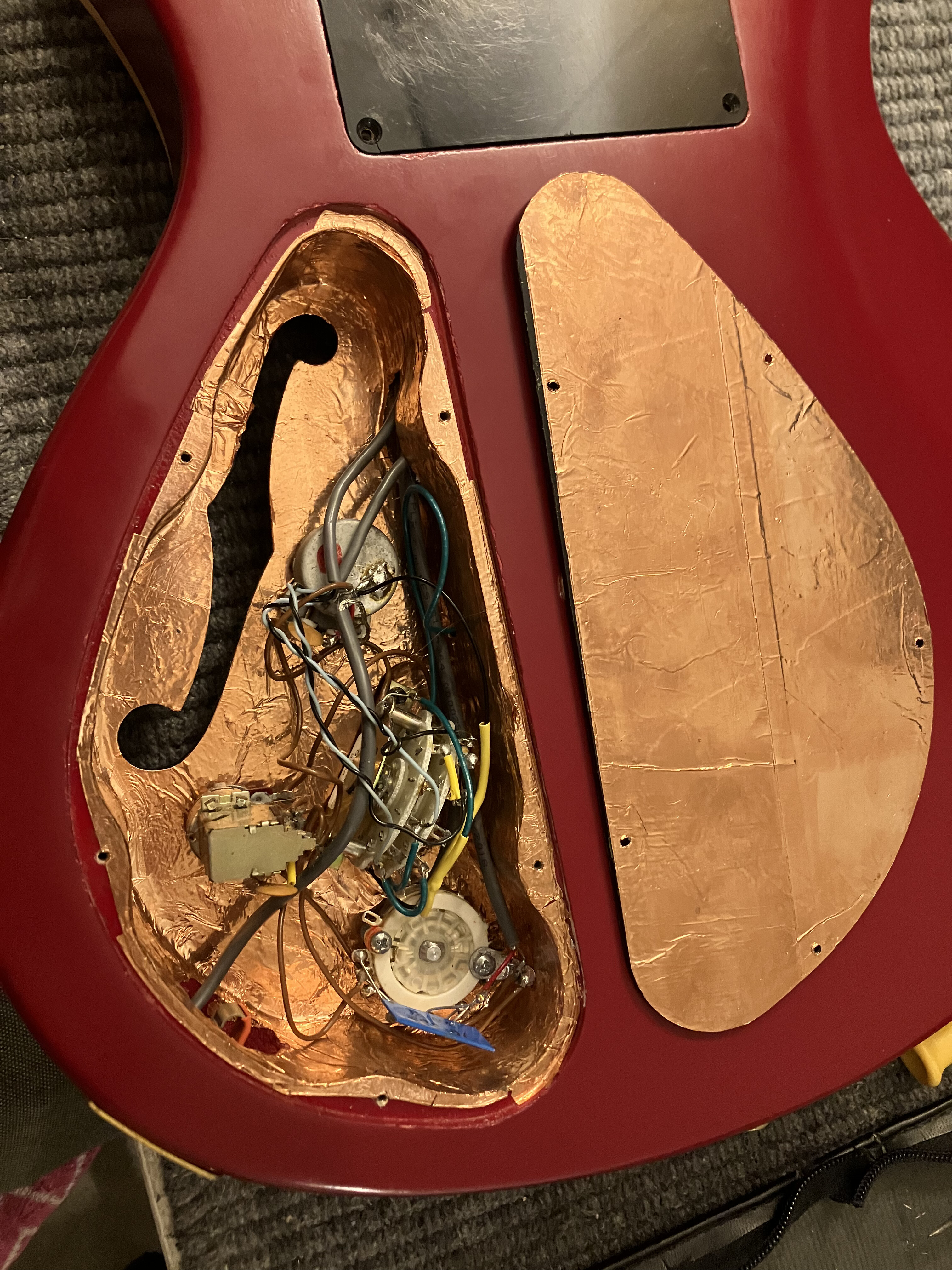
Figure 6: shiny copper shielding
One thing that made a big improvement was rewiring the dummy coil. I got curious about how it worked and so I desoldered it from the circuit and did some comparisons. Without the dummy coil, hum was bad. With the dummy coil, it was better. But here's where it got interesting. Changing the orientation of the dummy coil made a difference in the hum rejection. This should make sense if you've used "stacked" single coil pickups, as they are typically a single coil pickup with a second coil underneath, where the pole pieces may not extend through the far coil, making it a sort of co-axial dummy coil.
I noticed the best hum rejection when the dummy coil was directly below the selected pickup, but flipping it 180° would either improve or worsen the hum rejection depending on which pickup was selected.
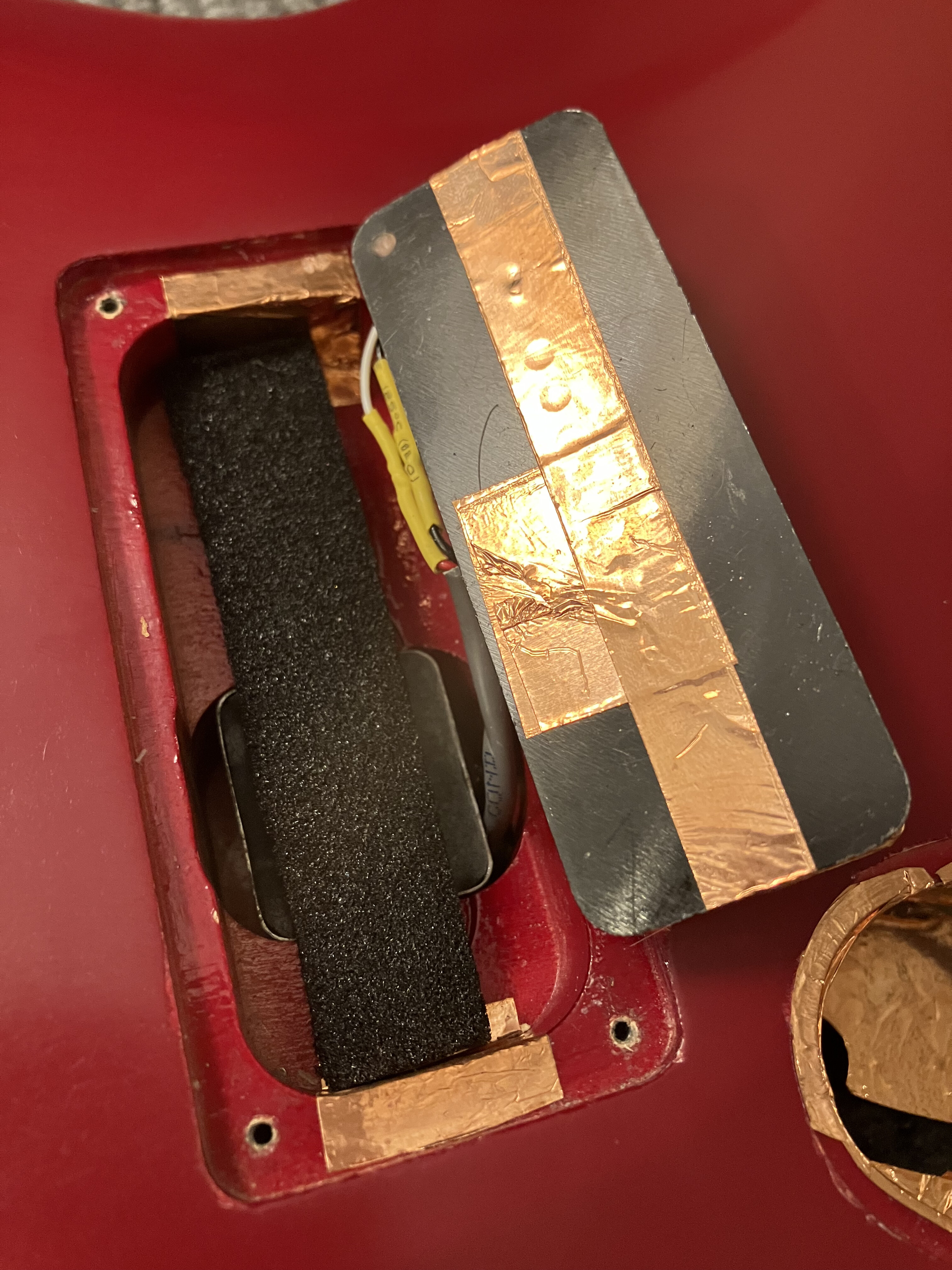
Figure 7: rewired dummy coil
I put a bit of foam between the dummy coil and the choke, and also shielded one side of the dummy coil and ensured all the shielding areas made contact with each other. Again, this is not for hum but for high frequency noise rejection. And I don't have hard evidence that it works, but as long as the shielding is in electrical contact with ground (and nothing else) it probably doesn't hurt to have it.
One clever thing the Blueshawk does is use reverse-wound, reverse-polarity pickups for the bridge and neck. This means when both are selected, the output is hum canceling. However, this seemed to present a catch-22 when using either pickup with the dummy coil, because it seemed like the dummy coil would either be right for the bridge pickup and wrong for the neck pickup, or vice versa.
Eventually I had flipped the dummy coil around enough times that I forgot which side was the original. But I found a configuration with what I believe to be less hum than the original. I suspect it was either wired backwards or placed upside down with respect to the optimal configuration.
Actionable Advice
Given my experience I can recommend a couple ideas that might improve your Blueshawk experience:
Hum with the neck or bridge pickup by itself?
First confirm all the wiring is correct. If it is, try re-orienting the dummy coil by flipping it over in its cavity. Keep the orientation with the least amount of hum. Alternatively, disconnect the dummy coil wiring and try the opposite polarity. Then repeat the orientation exercise. Keep the polarity/orientation with the least hum.
shield?
As long as you take care to avoid shorting out any signal wires, and ensure 100% of the shield is grounded, I think this is worth doing. A roll of copper tape with conductive adhesive is a few dollars and contains enough to shield several guitars.
audio taper volume pot?
This is on my to-do list. 300k audio taper pots with the right length of shaft are not common but they can be found. 500k and 250k pots are common and would work but might change the sound. I will try to source a 300k audio taper pot just to keep it close to the original sound, but my second choice would be 250k. It would be a little darker and a little less output but I think it would be closer to the original in terms of performance, especially considering a 250k pot will be less sensitive to different input impedances.