Simple Overdrive
Putting my ego aside to build a decent overdrive pedal.
Classic Overdrive Circuit
In my mind, the classic overdrive circuit is the inverting opamp with clipping diodes in the negative feedback loop. This clipping configuration always blends in a small amount (unity gain actually) of the clean signal which adds some clarity especially to lightly distorted sounds. In addition to the basic clipping section, pedals often also incorporate heavy filtering so it effectively becomes a mid-boost that can push an amplifier into overdrive without getting muddy (too much bass) or harsh (too much treble).
I used to think this circuit sounded bad (or at least, not my cup of tea), but coming back to guitar effects building after a long hiatus, I changed my mind.
Questing for Novelty
Don't try to impress anyone. You're brave, we all know that. Be simple, be direct. Nothing fancy.
-Stilgar
When I started designing a circuit of my own around this building block, I wanted to put my unique stamp on it. To be creative and bold, and above all novel. I tried asymmetric clipping diodes. I tried mosfet conduction clipping. I tried 2nd order lowpass filters, biquad filters, notch filters. But while these attempts were interesting, I wouldn't say they were satisfying, so I kept experimenting. Eventually I began to simplify and worried less about making a novel circuit. I ended up pretty close to the original starting point.
Maybe I had to try a bunch of different sounds before I could appreciate the "standard" circuit. Or maybe it was just my own hubris makign me think I could do it better. But at this point I feel like I've shed most of my ego about it and am able to hear it with fresher, less prejudiced ears.
An Incremental Improvement
This is the circuit I prefer as of right now (simulation). For me it is an improvement over the classic circuit both in terms of the sounds it makes as well as the range of adjustment offered. Of course this is all subjective and it might sound worse to you. But I'm making the schematic available here so nobody has to take my word for it - anyone with the parts and inclination can build it to judge for themselves.
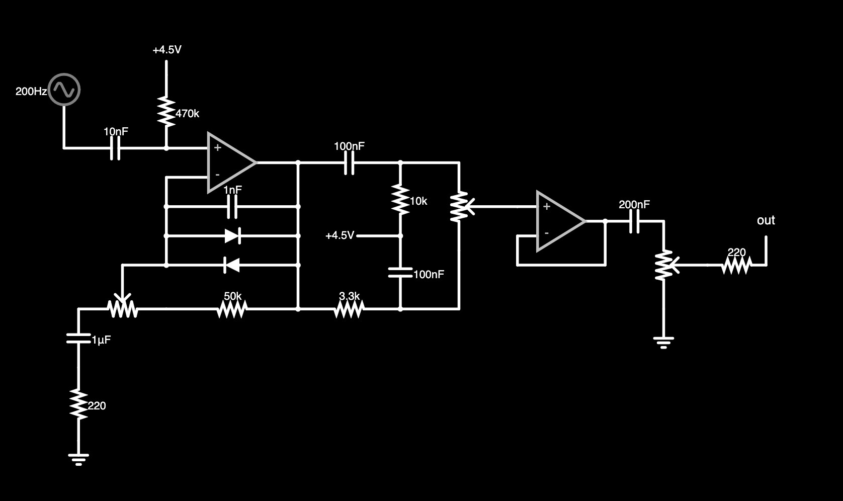
Figure 1: schematic
I'm still using up a pile of 10k potentiometers so the gain control arrangement and part values are a little unusual. But despite the unusual appearance, the function is similar to what you'd expect from a TS-9 or DS-1. The voltage gain varies from approximately 6 to approximately 270, whereas a TS-9's gain can be adjusted from about 10 to about 110. This might seem like a big difference but these are theoretical values for an idealized opamp. Real opamps fall short in terms of gain and bandwidth so the circuit on my breadboard might top out with a gain closer to 100 anway. One trade-off to note: because this is a linear taper potentiometer, the gain jumps dramatically in the last 5% or so of its rotation. I don't mind this quirk but I think most players would prefer a logarithmic taper pot for easier adjustment throughout the range of the control.
Rather than a treble boost/cut control, the tone control here is a pot that blends between a highpass and a lowpass, similar to the Big Muff distortion's tone control. The values in mine are tweaked so there's no midrange scoop, and it ends up acting like a "tilt" tone control. Clockwise is treble boost / bass cut, counterclockwise is the opposite. In the center is a frequency curve that I hear as "flat". This is a bit of a perceptual trick because the frequency response is actually a gentle treble cut in the "flat" position, but the added high frequency harmonics from the preceding clipping stage make it feel brighter.
There's a unity-gain buffer isolating the tone control from the output volume control, which I found to be enough to let the output be higher than unity gain even with the drive and tone controls at their minimum values. Again, a linear taper pot is not ideal in this position (audio taper would be better).
Below are plots of the frequency response at different tone control settings using Falstad's filter simulator.
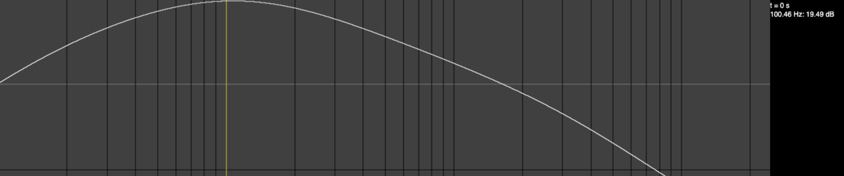
Figure 2: frequency response (Drive=0, Tone=0)
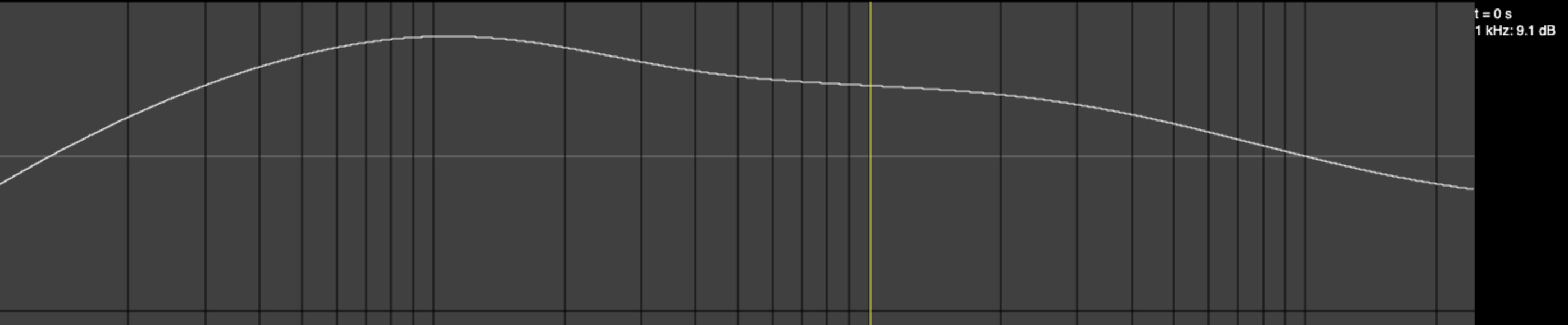
Figure 3: frequency response (Drive=0, Tone=0.5)
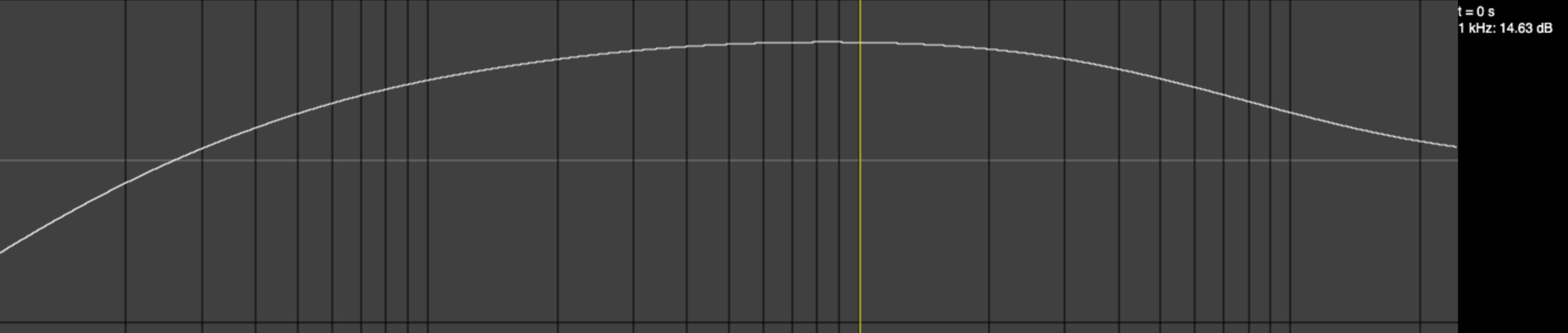
Figure 4: frequency response (Drive=0, Tone=1)
The frequency responses are similar as you adjust the drive control, so I didn't bother to make images of them. You can check out the simulation and adjust the controls yourself if you're curious.
Rehoused
Next steps are to transfer this from the breadboard to an enclosure. I'll probably reuse the enclosure from a previous build.