Dirt Boxes
A collection of in-progress guitar distortion circuits.
SRPP Stages
This design started with the BSIAB2 circuit, then I changed the mu-amp gain stages to SRPP gain stages, changed the gain control, and changed tone stack (simulation). The end result still has a lot of the same vibe as the original, and at the coarsest-grained level it's essentially unchanged, but all the specifics are different.
I typically prefer to work with opamps for analog audio because biasing is simpler than discrete transistors. But there is a lot of merit in the idea of interleaving tone filtering with clipping stages. Different flavors of clipping are easier to achieve when you can use one gain stage as a clean or slightly distorted boost and then drive a subsequent gain stage harder but only at specific frequencies.
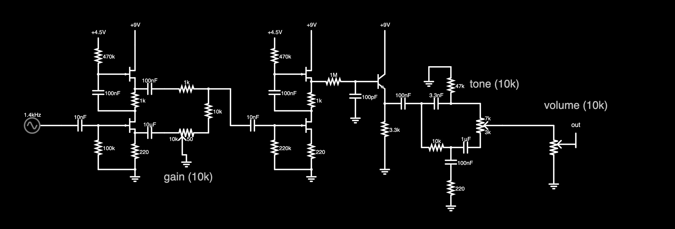
Figure 1: two cascaded SRPP gain stages, followed by a buffer, then tone and volume
I think this design still needs some refinement (especially in the tone stack) before I could claim it sounds amp-like, but the SRPP gain stages provide a good-sounding starting point. If I have any complaints about this circuit at the moment it would be that it has too much gain with the values shown. It's more like the "lead" channel of an amp, whereas I think I want it to be more like the "crunch" channel. Perhaps rather than trying to make one circuit do all things, I should just embrace what it does well and if I really want more from the circuit, put a toggle in to drop the gain range down to milder levels.
Soft Clipper 2025
Something went awry with the soft clipper I boxed up late last year (the clipping tone seemed to drop in volume while the clean sound came through as normal) but rather than spend more time debugging it I started designing its replacement (frequency response, clipping sim). I still like the idea of a 2-in-1 overdrive/boost pedal, but I think I want to do a buffered bypass and raise the max gain of the boost just a little bit. Some commercial pedals have a toggle to put the boost either before or after the drive, which also seems useful, just maybe not useful enough to me to justify the space required for an extra panel-mounted switch.
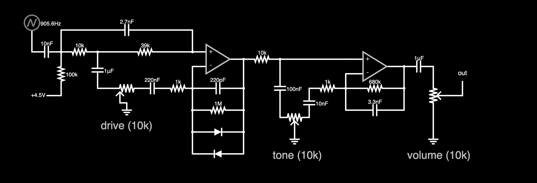
Figure 2: a somewhat novel take on the classic "soft clipping opamp overdrive followed by treble eq"
The fundamental architecture of this circuit is the same as you can find in the Ibanez Tube Screamer, Boss SD-1, and countless other pedals. However there are some novel tweaks inspired by the fact that I have a big pile of 10k ohm potentiometers that I want to use up before I order more parts.
The drive and tone controls here work roughly the same way, by panning between one setting or another. Turned to minimum, the drive control engages a bridge-T notch filter with a center frequency of about 150Hz. Turned to maximu, the notch disappears and it becomes more of a wide-range mid boost. The tone control pans between a treble cut and a treble boost, but with different cutoff frequencies. Credit for this tone control design goes to Mark Hammer.
The design goals of this circuit are:
- 10k pots
- wide range for gain/tone controls
- above unity gain even with drive/tone at minimum settings
- not overly dark at low gain
In the simulation at least, I've met these goals, although prototyping on a breadboard will have the final say. Here are some frequency response plots showing that this has a bit of a different character than the more conventional soft clipping overdrive (at least in the frequency response curves - this sim does not show clipping).
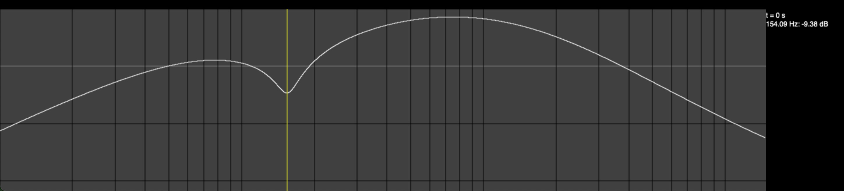
Figure 3: gain and tone at minimum (note -9dB at 154Hz, +17dB at 748Hz)
Note: the y-axis scale is different for the following plots.
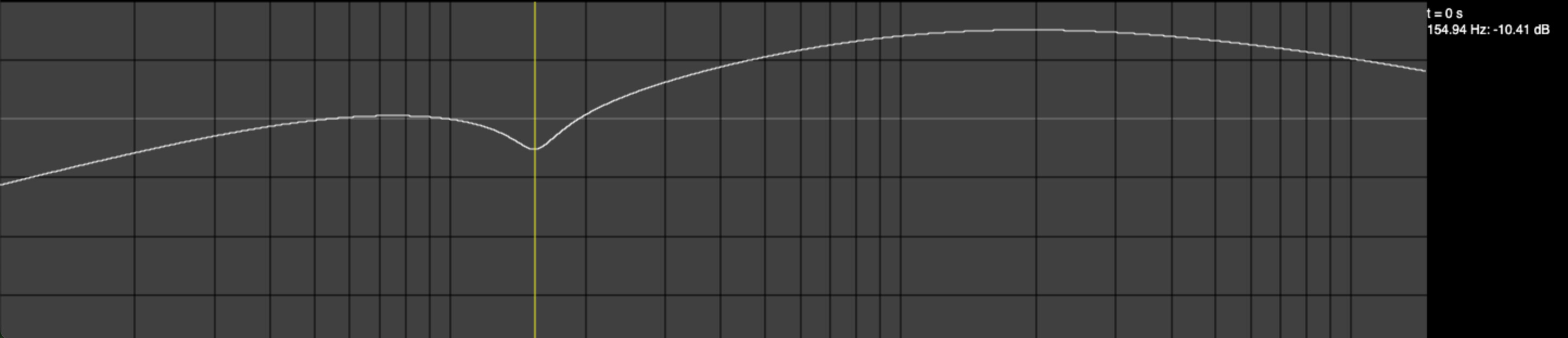
Figure 4: gain min, tone max leaves the 154Hz notch, but peaks at +29dB at 2kHz
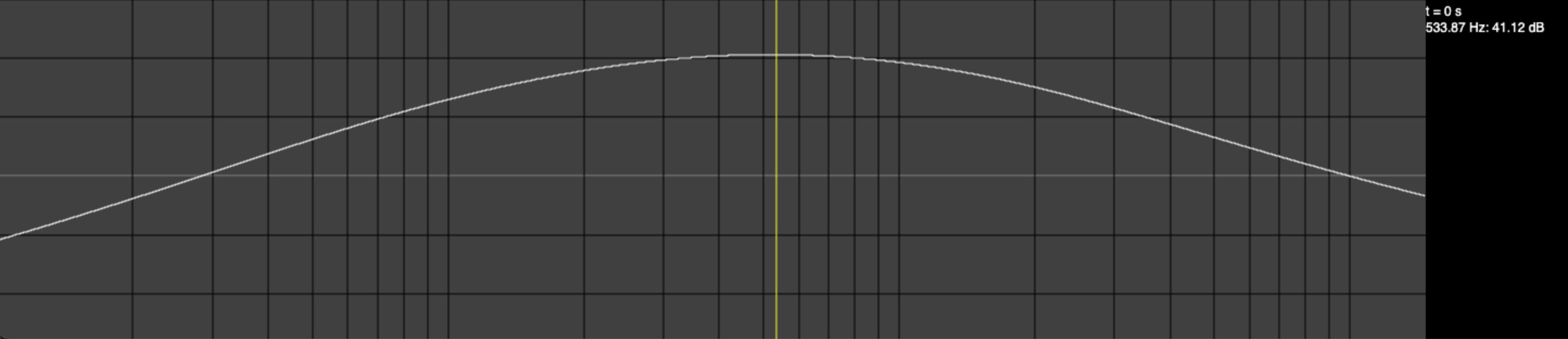
Figure 5: gain max, tone min looks like a broad 500Hz bandpass at +40dB
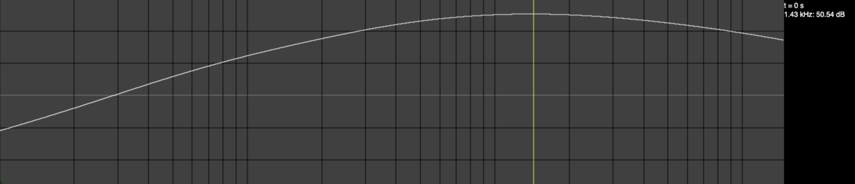
Figure 6: gain max, tone max shifts the peak to about 2kHz at +49dB
The opamps in this simulation are ideal, with a gain-bandwidth product at 1MHz, so plugging in real opamps will likely reduce the total gain as well as the Q of the notch filter.
As for how the clipping looks, it's harder to show with static images. But with the tone at about half and the drive at max, a 370Hz waveform should be soft-clipped as in this plot:
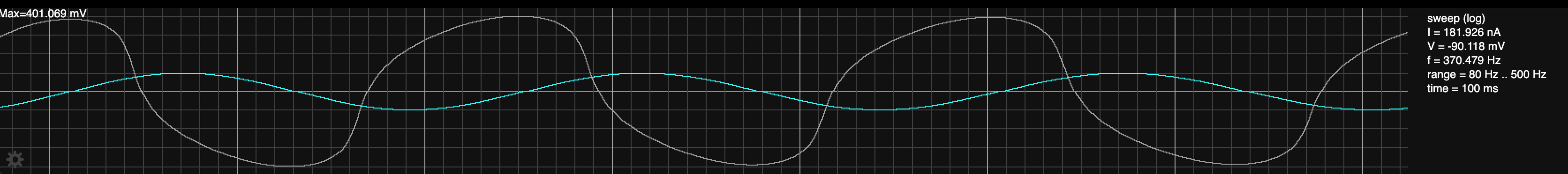
Figure 7: input (blue) and output (gray)
PWM Sample-Hold
This is an iteration of something I designed in the Before Times. The core is still a sample-hold circuit driven by a PWM, and the PWM is still derived from two Schmitt trigger oscillators. There's a low frequency oscaillator (LFO) and a higher-frequency oscaillator (carrier) with the intent being that the LFO frequency is variable from 0.1Hz-10Hz while the carrier frequency is variable from audio range to over 20kHz. The old version of this circuit had a window comparator indended to act as a gate, but when I simulated it, it did not work. So now the gate function is a more conventional peak detector followed by a threshold to mute the carrier when the input level gets too low. This new gate seems to work in the simulation, so we'll see if that translates to reality when I build it.
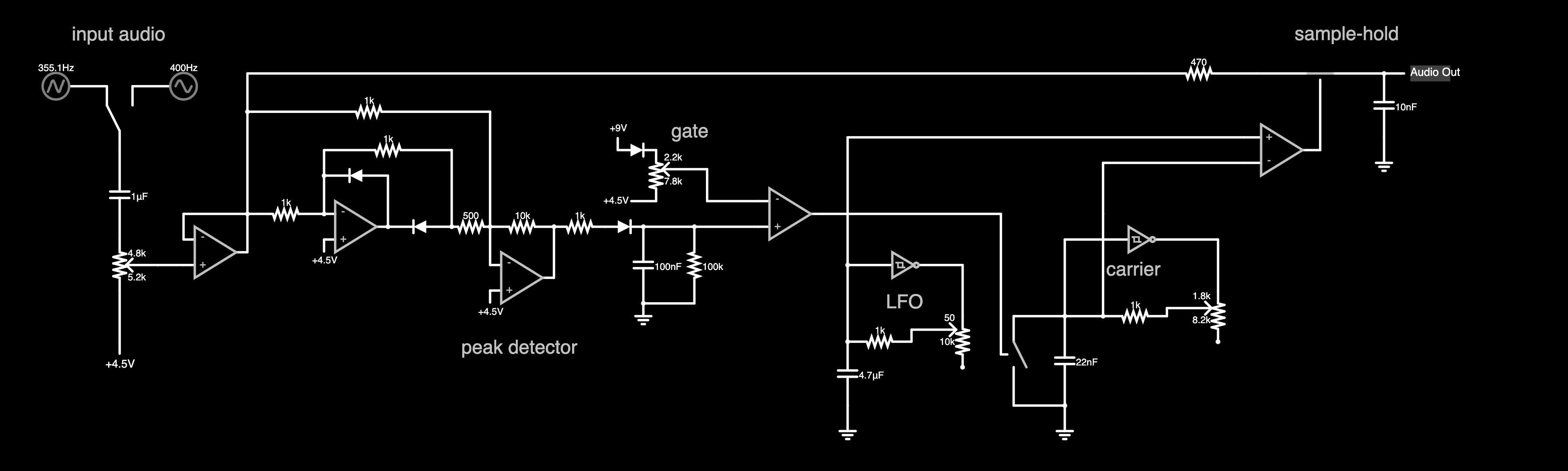
Figure 8: pwm controls an electronic switch, duty cycle is difference between two triangle waveforms, carrier oscillator muted when input envelop drops below threshold
It might make more sense to call this a modulation effect rather than a distortion, but because the sample-hold feature produces a square-topped waveform you could make the argument for calling it a distortion or fuzz. If the carrier is set to audio frequencies it should sound like a ring modulator. With the carrier above audio frequencies, it might sound more like fizzy smearing of the waveform.
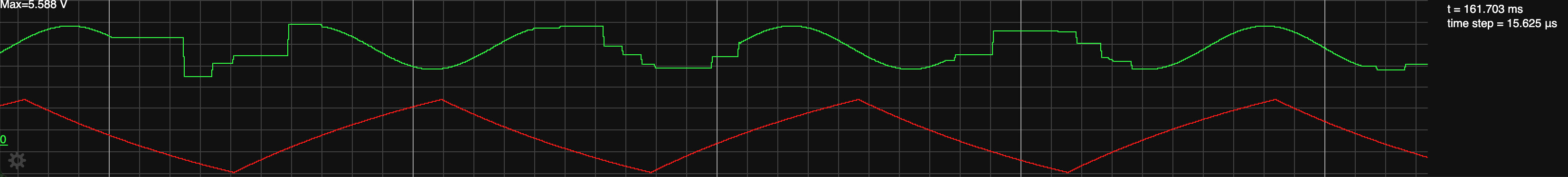
Figure 9: output (green) and LFO waveform (red)
The effect only occurs when the LFO waveform drops below the carrier waveform (not shown). It's despite the ragged appearance of the waveform, the "steps" are changing in sync with the carrier waveform which is at audio rates or higher. So it should sound like it's affecting the timbre more than the dynamics of the original sound.
This schematic highlights the LFO and PWM control. The audio path remains minimal - just one resistor, one capacitor, and a switch. However, my more ambitious and longer-term plan is to use this oscillator control as a platform for more effects. The switch acts as a variable resistor and there are a lot of circuits that get interesting when you vary certain resistance values with an LFO.
It is probably worth stepping back a bit from this oscillator to reflect on how one might achieve the same PWM-controlled resistance without any preconceived notion of how I've done it here. Microcontrollers are cheap and there may be fast-enough PWMs available to make that a better solution. From a black-box reverse engineering perspective, what we have is just:
- PWM, with duty cycle computed by the difference of two oscillators
- LFO (sub-audio range)
- carrier (audio frequency and above)
- gating of the carrier
These features could reasonably be encoded in a microcontroller with a smaller footprint than one of the chips used in the above design. So maybe that's a better approach. I'll have to think about it. There's fun in the analog approach for sure, but writing a program for a microcontroller is a different kind of fun.