Guitar Effects
In a previous life, I designed guitar effects. Here are some fragments which survived digital bitrot.
The "MS Paint Period"
For a while I was drawing schematics "by hand" in MS Paint. I had a template file with various hand-drawn components, which I would then copy-and paste into each new drawing.
Not really a guitar effect, (although at least 1 person did use it in a guitar effect) but it's my favorite discovery. I call it a "folding" flash ADC.
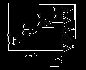
This version shows a 5-bit ADC, where the output of the each comparator provides the voltage reference to the next lower bit. The "recursive" construction causes propogation delay due to the the successively lower bits flipping before the output stabilizes. This circuit doesn't have any real practical advantages to the cheap successive-approximation ADC, or the fast flash ADC, but occupies a niche somewhere in between the two types.
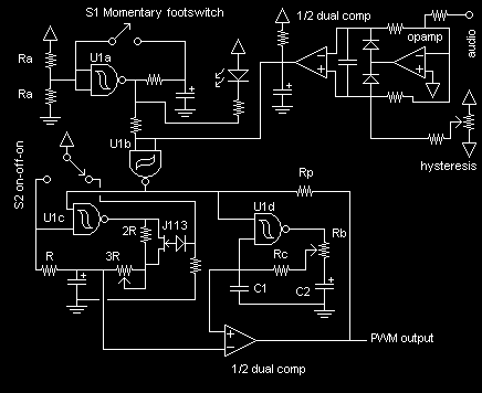
Next is a series of effects containing a PWM-based oscillator made from some Schmitt-trigger NAND gates plus a comparator. The CD4093 has 4 CMOS 2-input Schmitt trigger NAND gates in one package. In this circuit an op-amp (1/4 of a quad JFET-input TL074) is used in place of a true comparator.
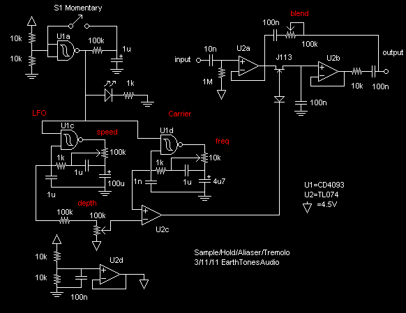
There are 3 fun tricks going on in the upper left corner. First is U1a which acts as a toggle flip-flop. Whenever S1 closes, the output of U1a toggles. The nice thing about this circuit is that, due to the internal bias circuitry of the CD4093, the output always comes up low at power-on.
Next is the combination of "LFO" and "Carrier" oscillators. The Carrier is adjustable from (roughly) 20Hz to 1MHz. The LFO is adjustable from (roughly) 0.1Hz to 1kHz. Comparator U2c takes the exponential sawtooth from the input of each NAND and produces a PWM output. By setting the Carrier oscillator above audio range, the output of the comparator is essentially a PWM-encoded version of the LFO. Adjusting the Carrier down to audio ranges allows for more complex waveforms. The depth control allows for attenuating the LFO signal before it reaches the PWM converter.
Finally, the PWM output is used to toggle a J113 "analog switch" in a sample-and-hold circuit between 2 unity-gain buffers. At high frequencies, it acts more like a variable attenuator than a true sample-hold circuit. The overall effect is then adjustable from traditional tremolo style sounds to glitchy noise and aliasing sounds.
This next circuit is a variation on the above theme. Same LFO+Carrier+PWM, but this time using a CD4066 quad SPST analog switch. There is an added on-off-on toggle switch to provide 3 different speed ranges to the U1c oscillator. No values are specified in this schematic, which leads me to believe I didn't actually build it.
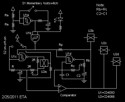
Finally is another variation on the theme, again with a 3-speed selector, but this time under JFET control instead of a CMOS switch. While the full audio path is not shown, there is a gating circuit in the upper-right corner which is driven by the audio signal. When the audio signal is outside the window comparator's thresholds (set by the "hysteresis" control and the 2 diodes) the oscillator is on. Otherwise when the audio level drops below these thresholds the oscillators stop:
Fuzz
This is a distortion/fuzz circuit originally developed as part of a DIY/commercial collaboration. It ended up not being used so now it's open source! The somewhat unique features of this circuit include a low input impedance, which means if it's the first effect after a passive guitar, you can use the guitar's volume control to "clean up" the distortion. It also has a unique tone control that I've not seen used anywhere else, which pans between mid cut, mid boost, and treble boost. It's very high gain and requires a clean wiring layout or it will oscillate.
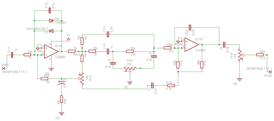
I actually built this one in real life.
Recycled Content
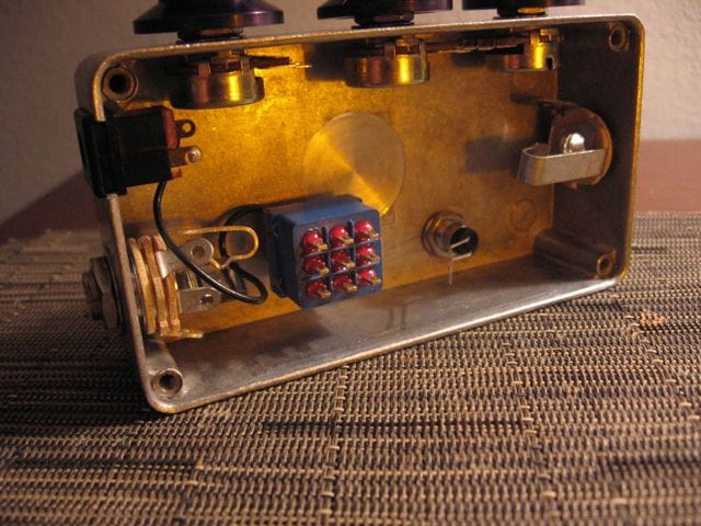
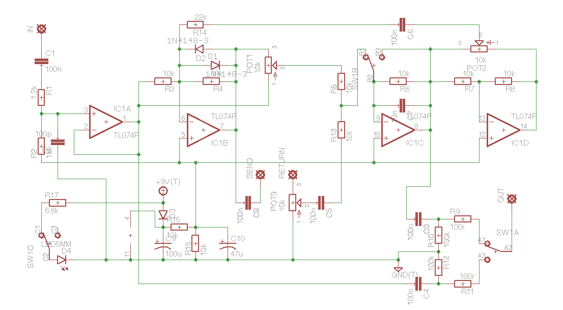
This is a rehoused multi-effect unit from my old Crate GFX combo amp. I removed the multi-effects unit from the amp and reworked its effect selector knob to be a 4-position switch. This disabled the cheesy slapback and flanger effects and kept the reverb and reverb+chorus effects. The enclosure is machined from recycled aluminum scrap, and the knobs are machined from recycled steel scrap.
This is the splitter/mixer circuit used to blend the straight signal with the effected signal:
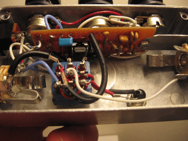
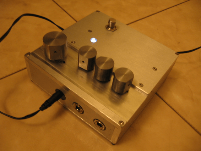
And here is the final build:
Highly Experimental
This is an untested idea for an octave-down effect, based on phase shift and using the same polarity switching at derivative=0 as used in the Boss OC-2 pedal.
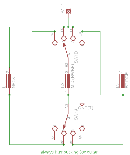
Pickup Switch
Also not really a guitar effect, but an idea for a switching scheme for the common 3-single-coil pickup guitar. Instead of the traditional 5-way switch arrangement:
neck
middle+neck in parallel
middle
bridge+middle in parallel
bridge
…this uses a 4-way switch where each combination has 2 coils:
middle+neck in series
middle+neck in parallel
bridge+middle in parallel
bridge+middle in series
When the middle pickup is reverse-wound and reversed magnetic polarity with respect to the other pickups, then the combination of middle+other cancels hum. The reason for the 4-way switch and the different series/parallel connections is to roughly mimic the "lead" and "rhythm" progression. This mimicry isn't perfect, because the series connection is always louder and bassier than the parallel connetion, but it's a compromise between usefulness and versatility.